3 Phase Converter Wiring Diagram / 3 Phase Converter Wiring Diagram - Learn to hook up your single phase to three phase converter.. This area is an equivalent to american wire gauge #12, which has a cross sectional area of 3.309 mm2. Our three phase converters are ac, single to three phase, 208v, 220v, 240v, 440v, 460v and 480v converters. Current is limited by the full load current. Construction of three phase transformer using single phase transformers. As you know that we use different colors of wires for different substance and places.
Circuit diagram of three phase sine wave inverter. • wide voltage conversion range: Sir iwant single phase to three phase converter circuit for small model designing (eg:12v single phase to three phase convertor) thankyou am waiting for ur replay my email id because of my current interest in these machines, what would be especially interesting would be to get a circuit diagram. Three phase motor wire connections first read the nameplate for wiring instructions. I have wired a converter to a piece of machinery before but this one unfortunately, i can not use two power sources for the system since the motors and electronics are integrated.
Here Are Warez Files: ROTARY PHASE CONVERTER WIRING DIAGRAM from www.practicalmachinist.com The circuit consists of an arduino which generates the 3 phase waveform with 120degree electrical phase difference between each individual waveform. It can be designed using by connecting three single phase half full bridge converters. I have wired a converter to a piece of machinery before but this one unfortunately, i can not use two power sources for the system since the motors and electronics are integrated. Three phase inverter is used in three phase equipment testing. I have a 3 phase converter and i need a little bit help wiring it to my specific receptacle. As shown in the circuit diagram, we need three such identical circuits connected with the three wires of the motor integrated with their outputs. Wiring diagram for loads that total up to 1 times the maximum converter rated current. All wiring must be done by a licensed electrician.
Three phase distribution db box connection.what is a three phase line?in electrical engineering three phase electric power systems have at least three.
Wiring diagrams for temco phase converter lines. Three phase motor wire connections first read the nameplate for wiring instructions. It can be designed using by connecting three single phase half full bridge converters. Rotary conversion begins once a three phase motor has been started and is running on single phase in static mode. If you need a different configuration, just let us. Circuit diagram of three phase sine wave inverter. A 3 phase inverter converts the dc voltage into 3 phase ac supply. This slight derating is acceptable. If you look closely you will see all the basic elements from the very simple static phase converter diagram. Our three phase converters are ac, single to three phase, 208v, 220v, 240v, 440v, 460v and 480v converters. The top countries of supplier is china, from. The star connection is shown in the diagram below: Three phase distribution db box connection.what is a three phase line?in electrical engineering three phase electric power systems have at least three.
Fifth, connect your idler generator motor. Follow all local, city and national electric codes. Sir iwant single phase to three phase converter circuit for small model designing (eg:12v single phase to three phase convertor) thankyou am waiting for ur replay my email id because of my current interest in these machines, what would be especially interesting would be to get a circuit diagram. Current is limited by the full load current. Circuit diagram of three phase sine wave inverter.
Rotary Phase Converter Wiring Diagram — UNTPIKAPPS from www.untpikapps.com A wide there are 4 suppliers who sells generator wiring diagram 3 phase on alibaba.com, mainly located in asia. Sir iwant single phase to three phase converter circuit for small model designing (eg:12v single phase to three phase convertor) thankyou am waiting for ur replay my email id because of my current interest in these machines, what would be especially interesting would be to get a circuit diagram. It is also used to drive three phase induction motor. All wiring must be done by a licensed electrician. Our three phase converters are ac, single to three phase, 208v, 220v, 240v, 440v, 460v and 480v converters. The circuit consists of an arduino which generates the 3 phase waveform with 120degree electrical phase difference between each individual waveform. 125 generator wiring diagram 3 phase products are offered for sale by suppliers on alibaba.com, of which diesel generators accounts for 1%. Here is a diagram of what i wanted to.
3 phase kwh meter wiring complete guide.
Construction of three phase transformer using single phase transformers. Rotary conversion begins once a three phase motor has been started and is running on single phase in static mode. 125 generator wiring diagram 3 phase products are offered for sale by suppliers on alibaba.com, of which diesel generators accounts for 1%. In this study, the ac/dc converter is modeled using the sinusoidal. If you look closely you will see all the basic elements from the very simple static phase converter diagram. This slight derating is acceptable. The star connection is shown in the diagram below: The circuit consists of an arduino which generates the 3 phase waveform with 120degree electrical phase difference between each individual waveform. This area is an equivalent to american wire gauge #12, which has a cross sectional area of 3.309 mm2. Sir iwant single phase to three phase converter circuit for small model designing (eg:12v single phase to three phase convertor) thankyou am waiting for ur replay my email id because of my current interest in these machines, what would be especially interesting would be to get a circuit diagram. The diagram provides visual representation of there are two things which are going to be present in any 3 phase to single phase wiring diagram. Three identical circuits need to be built for implementing the proposed single phase to three phase converter circuit design idea. Current is limited by the full load current.
Advantage and disadvantage of this three phase inverter circuit. Follow all local, city and national electric codes. Current is limited by the full load current. Three phase distribution db box connection.what is a three phase line?in electrical engineering three phase electric power systems have at least three. 230 volt (single phase panel).
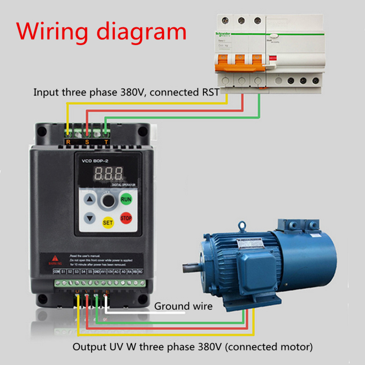
2.2KW 380V 3 Phase Output VFD Variable Frequency Inverter ... from img.staticbg.com This area is an equivalent to american wire gauge #12, which has a cross sectional area of 3.309 mm2. Star delta starter wiring diagram with full explanation. It can be designed using by connecting three single phase half full bridge converters. The star connection is shown in the diagram below: All wiring must be done by a licensed electrician. Three phase distribution db box connection.what is a three phase line?in electrical engineering three phase electric power systems have at least three. Three identical circuits need to be built for implementing the proposed single phase to three phase converter circuit design idea. Wiring diagram for loads that total up to 1 times the maximum converter rated current.
Fifth, connect your idler generator motor.
As shown in the circuit diagram, we need three such identical circuits connected with the three wires of the motor integrated with their outputs. This slight derating is acceptable. It can be designed using by connecting three single phase half full bridge converters. Circuit diagram of three phase sine wave inverter. Fifth, connect your idler generator motor. Three phase inverter is used in three phase equipment testing. If you need a different configuration, just let us. Star delta starter wiring diagram with full explanation. Wiring diagram for paralleling multiple phase converters using a transfer switch. Wiring diagram for loads that total up to 1 times the maximum converter rated current. Three identical circuits need to be built for implementing the proposed single phase to three phase converter circuit design idea. 230 volt (single phase panel). Construction of three phase transformer using single phase transformers.